Electronics and Arduino#
Hardware#
The first things we needed to find were the hardware components of our system. We needed :
- A microcontroller
- A breadboard
- A battery
- A microphone
- A LED, resistors and cables
Breadboard, LED, cables and resistors were easy to find at the FabLab. For the microphone, 2 kinds were available: the VMA309 analogical microphone and the INMP441 digital microphone. We chose the digital one for 2 reasons: it detects sounds with an intensity up to 120 dB while the KY-038 only detects sounds between 48 and 66 dB, which is not suitable for our project. Additionnaly, it is way smaller, which is perfect for a portable device.
The problem with this digital microphone is that it communicates with the microcontroller through an I²S interface (look here for an explanation), which was not implemented on the RP-2040 microcontroller hardware we received during the formation. Axel told us that we could also implement it using the Arduino software, but first of all we don’t really have the coding competences to understand that and it seems that the system will not be as exact as the one implemented on the hardware anyway. Good news, Axel had an XIAO ESP-32-S3 microcontroller in stock, which first of all has an I²S interface but is also way smaller than the RP-2040 (it’s smaller than a thumb). Additionnaly, Axel gave us a small, rechargeable and portable 3.7V battery to aliment our prototype. We now had all the hardware we needed and we could focus on the wiring and the software.
Wiring and software#
This is were we got really, really lucky. First of all, there is a complete YouTube tutorial by ThatProject on the ESP32 microcontroller and the microphone. Then, we also found a GitLab tutorial for a sound sensor using the ESP32. This code implements various microphones, among those the one we used, as well as an option for an A-filtering (dBA, which we finally did not use). It’s basically all we needed. Credits to Ivan Kostoski for creating this work. The only issue we faced was that the standard ESP-32 controller is a bit different from our miniaturized version (mainly because it has less pin’s), so we needed to experiment a bit (we burned 2 microphones and one battery during the process…).
Here you can see the wiring on a prototype and on a scheme:

We finally came up with a system that includes a red LED that lights up when the filtered sound level (dB) reaches a certain threshold. We chose 4 thresholds based on the european norms for sound safety which we reduced between 33% and 50% more or less because once that threshold is reached, the damage is already done. We want to prevent that to happen.
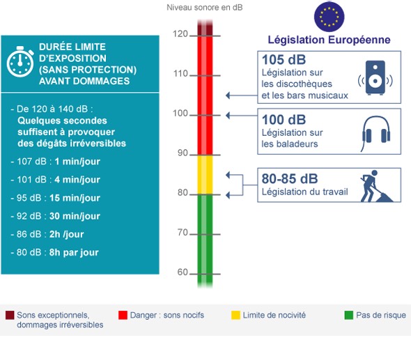
The LED lights up when :
- The sound level exceeds 110 dB
- The mean value (dB) over 2 minutes exceeds 101 dB
- The mean value (dB) over 10 minutes exceeds 95 dB
- The mean value (dB) over 1 hour and 20 minutes exceeds 86 dB
We also wanted to implement a switch in order to reduce electricity consumption of the battery.
A calibration process was also necessary in order to get satisfying results from the microphone. For that we used a real noise sensor to calibrate ours and we added that calibration term into our code.
Code#
The code is extremely long, but why exactly? And what makes it good?
- It includes an A-filtering option (which was our initial pla, we finally rejected the idea because the damages done to the ear are more linked to the dB scale) adapted to a digital signal, which is what we have here.
- It takes the datasheet of our microphone (Offset, noise floor, sound to noise ratio, frequency response, …) into account which gives us a better data output
- It has been made by Ivan K., an electrical engineer from Skopje, MK.
- The GitHub page of the project is really detailed, with MatLab filtering curves, datasheets for various microphones and explanations on the filtering done.
- It’s however far from perfect, we needed to include a calibration term in order to make the dB values exact
To summarize, what our code does is the following :
- Introduction, licensing etc (line 1-41)
- Initializing of the pins, the filtering used (dB) and of the constant values (lines 42-85)
- Digital filtering (line 86-140). Eventually, we didn’t need that part
- Sampling task and microphone setup, basically this is just telling the ESP32 how to process the data from the microphone (lines 141-263).
- Void Setup{} (lines 263-296). Creating the tasks.
- Void Loop{} (line 264-357). Executing the tasks, like computing and reading dBA values and controlling the LED.
The calculations for the dB value are made using the following formula : Leq_dB =
20 log (I/Iref) is the standard formula for sound intensity in dB.
/*
 * Display A-weighted sound level measured by I2S Microphone
 *
 * (c)2019 Ivan Kostoski
 *Modified 2023 by Lukas Schieble
 *
 * This program is free software: you can redistribute it and/or modify
 * it under the terms of the GNU General Public License as published by
 * the Free Software Foundation, either version 3 of the License, or
 * (at your option) any later version.
 *
 * This program is distributed in the hope that it will be useful,
 * but WITHOUT ANY WARRANTY; without even the implied warranty of
 * MERCHANTABILITY or FITNESS FOR A PARTICULAR PURPOSE.  See the
 * GNU General Public License for more details.
 *
 * You should have received a copy of the GNU General Public License
 * along with this program.  If not, see <https://www.gnu.org/licenses/>.
 */

/*
 * Sketch samples audio data from I2S microphone, processes the data
 * with digital IIR filters and calculates A or C weighted Equivalent
 * Continuous Sound Level (Leq)
 *
 * I2S is setup to sample data at Fs=48000KHz (fixed value due to
 * design of digital IIR filters). Data is read from I2S queue
 * in 'sample blocks' (default 125ms block, equal to 6000 samples)
 * by 'i2s_reader_task', filtered trough two IIR filters (equalizer
 * and weighting), summed up and pushed into 'samples_queue' as
 * sum of squares of filtered samples. The main task then pulls data
 * from the queue and calculates decibel value relative to microphone
 * reference amplitude, derived from datasheet sensitivity dBFS
 * value, number of bits in I2S data, and the reference value for
 * which the sensitivity is specified (typically 94dB, pure sine
 * wave at 1KHz).
 *
 * Displays line on the small OLED screen with 'short' LAeq(125ms)
 * response and numeric LAeq(1sec) dB value from the signal RMS.
 */

#include <driver/i2s.h>
#include "sos-iir-filter.h"

//
// Configuration
//

#define LEQ_PERIOD        1           // second(s)
#define WEIGHTING         None      // Also avaliable: 'C_weighting' or 'None' (Z_weighting)
#define LEQ_UNITS         "Leq"      // customize based on above weighting used
#define DB_UNITS          "dB"       // customize based on above weighting used
#define USE_DISPLAY       0

#define LEDPIN            D10
// NOTE: Some microphones require at least DC-Blocker filter
#define MIC_EQUALIZER     INMP441    // See below for defined IIR filters or set to 'None' to disable
#define MIC_OFFSET_DB     3.0103      // Default offset (sine-wave RMS vs. dBFS). Modify this value for linear calibration

// Customize these values from microphone datasheet
#define MIC_SENSITIVITY   -26         // dBFS value expected at MIC_REF_DB (Sensitivity value from datasheet)
#define MIC_REF_DB        94.0        // Value at which point sensitivity is specified in datasheet (dB)
#define MIC_OVERLOAD_DB   120       // dB - Acoustic overload point
#define MIC_NOISE_DB      33        // dB - Noise floor
#define MIC_BITS          24          // valid number of bits in I2S data
#define MIC_CONVERT(s)    (s >> (SAMPLE_BITS - MIC_BITS))
#define MIC_TIMING_SHIFT  0           // Set to one to fix MSB timing for some microphones, i.e. SPH0645LM4H-x
#define CALIBRATION       0           //To be verified
// Calculate reference amplitude value at compile time ; pow(10, */20) is the standard formula used to convert dB into linear values
constexpr double MIC_REF_AMPL = pow(10, double(MIC_SENSITIVITY)/20) * ((1<<(MIC_BITS-1))-1);

//
// I2S pins - Can be routed to almost any (unused) ESP32 pin.
//            SD can be any pin, inlcuding input only pins (36-39).
//            SCK (i.e. BCLK) and WS (i.e. L/R CLK) must be output capable pins
//
// Below ones are just example for my board layout, put here the pins you will use
//
#define I2S_WS            D0
#define I2S_SCK           D2
#define I2S_SD            D1

// I2S peripheral to use (0 or 1)
#define I2S_PORT          I2S_NUM_0

//
// IIR Filters
//

// DC-Blocker filter - removes DC component from I2S data
// See: https://www.dsprelated.com/freebooks/filters/DC_Blocker.html
// a1 = -0.9992 should heavily attenuate frequencies below 10Hz
SOS_IIR_Filter DC_BLOCKER = {
  gain: 1.0,
  sos: {{-1.0, 0.0, +0.9992, 0}}
};

//
// Equalizer IIR filters to flatten microphone frequency response
// See respective .m file for filter design. Fs = 48Khz.
//
// Filters are represented as Second-Order Sections cascade with assumption
// that b0 and a0 are equal to 1.0 and 'gain' is applied at the last step
// B and A coefficients were transformed with GNU Octave:
// [sos, gain] = tf2sos(B, A)
// See: https://www.dsprelated.com/freebooks/filters/Series_Second_Order_Sections.html
// NOTE: SOS matrix 'a1' and 'a2' coefficients are negatives of tf2sos output
//


// TDK/InvenSense INMP441
//IMPORTANT FOR OUR PROJECT
// Datasheet: https://www.invensense.com/wp-content/uploads/2015/02/INMP441.pdf
// B ~= [1.00198, -1.99085, 0.98892]
// A ~= [1.0, -1.99518, 0.99518]
SOS_IIR_Filter INMP441 = {
  gain: 1.00197834654696,
  sos: { // Second-Order Sections {b1, b2, -a1, -a2}
    {-1.986920458344451, +0.986963226946616, +1.995178510504166, -0.995184322194091}
  }
};
//
// Weighting filters
//

//
// A-weighting IIR Filter, Fs = 48KHz
// (By Dr. Matt L., Source: https://dsp.stackexchange.com/a/36122)
// B = [0.169994948147430, 0.280415310498794, -1.120574766348363, 0.131562559965936, 0.974153561246036, -0.282740857326553, -0.152810756202003]
// A = [1.0, -2.12979364760736134, 0.42996125885751674, 1.62132698199721426, -0.96669962900852902, 0.00121015844426781, 0.04400300696788968]
SOS_IIR_Filter A_weighting = {
  gain: 0.169994948147430,
  sos: { // Second-Order Sections {b1, b2, -a1, -a2}
    {-2.00026996133106, +1.00027056142719, -1.060868438509278, -0.163987445885926},
    {+4.35912384203144, +3.09120265783884, +1.208419926363593, -0.273166998428332},
    {-0.70930303489759, -0.29071868393580, +1.982242159753048, -0.982298594928989}
  }
};


//
// Sampling
//
#define SAMPLE_RATE       48000 // Hz, fixed to design of IIR filters
#define SAMPLE_BITS       32    // bits
#define SAMPLE_T          int32_t
#define SAMPLES_SHORT     (SAMPLE_RATE / 8) // ~125ms
#define SAMPLES_LEQ       (SAMPLE_RATE * LEQ_PERIOD)
#define DMA_BANK_SIZE     (SAMPLES_SHORT / 16)
#define DMA_BANKS         32

// Data we push to 'samples_queue'
struct sum_queue_t {
  // Sum of squares of mic samples, after Equalizer filter
  float sum_sqr_SPL;
  // Sum of squares of weighted mic samples
  float sum_sqr_weighted;
  // Debug only, FreeRTOS ticks we spent processing the I2S data
  uint32_t proc_ticks;
};
QueueHandle_t samples_queue;

// Static buffer for block of samples
float samples[SAMPLES_SHORT] __attribute__((aligned(4)));

//
// I2S Microphone sampling setup
//
void mic_i2s_init() {
  // Setup I2S to sample mono channel for SAMPLE_RATE * SAMPLE_BITS
  // NOTE: Recent update to Arduino_esp32 (1.0.2 -> 1.0.3)
  //       seems to have swapped ONLY_LEFT and ONLY_RIGHT channels
  const i2s_config_t i2s_config = {
    mode: i2s_mode_t(I2S_MODE_MASTER | I2S_MODE_RX),
    sample_rate: SAMPLE_RATE,
    bits_per_sample: i2s_bits_per_sample_t(SAMPLE_BITS),
    channel_format: I2S_CHANNEL_FMT_ONLY_LEFT,
    communication_format: i2s_comm_format_t(I2S_COMM_FORMAT_I2S | I2S_COMM_FORMAT_I2S_MSB),
    intr_alloc_flags: ESP_INTR_FLAG_LEVEL1,
    dma_buf_count: DMA_BANKS,
    dma_buf_len: DMA_BANK_SIZE,
    use_apll: true,
    tx_desc_auto_clear: false,
    fixed_mclk: 0
  };
  // I2S pin mapping
  const i2s_pin_config_t pin_config = {
    bck_io_num:   I2S_SCK,
    ws_io_num:    I2S_WS,
    data_out_num: -1, // not used
    data_in_num:  I2S_SD
  };

  i2s_driver_install(I2S_PORT, &i2s_config, 0, NULL);

  #if (MIC_TIMING_SHIFT > 0)
    //  manipulation of I2S peripheral registers
    // to fix MSB timing issues with some I2S microphones
    REG_SET_BIT(I2S_TIMING_REG(I2S_PORT), BIT(9));
    REG_SET_BIT(I2S_CONF_REG(I2S_PORT), I2S_RX_MSB_SHIFT);
  #endif

  i2s_set_pin(I2S_PORT, &pin_config);
}

//
// I2S Reader Task
//
// Rationale for separate task reading I2S is that IIR filter
// processing cam be scheduled to different core on the ESP32
// while main task can do something else, like update the
// display in the example
//
// As this is intended to run as separate hihg-priority task,
// we only do the minimum required work with the I2S data
// until it is 'compressed' into sum of squares
//
// FreeRTOS priority and stack size (in 32-bit words)
#define I2S_TASK_PRI   4
#define I2S_TASK_STACK 2048
//
void mic_i2s_reader_task(void* parameter) {
  mic_i2s_init();

  // Discard first block, microphone may have startup time (i.e. INMP441 up to 83ms)
  size_t bytes_read = 0;
  i2s_read(I2S_PORT, &samples, SAMPLES_SHORT * sizeof(int32_t), &bytes_read, portMAX_DELAY);

  while (true) {
    // Block and wait for microphone values from I2S
    //
    // Data is moved from DMA buffers to our 'samples' buffer by the driver ISR
    // and when there is requested ammount of data, task is unblocked
    //
    // Note: i2s_read does not care it is writing in float[] buffer, it will write
    //       integer values to the given address, as received from the hardware peripheral.
    i2s_read(I2S_PORT, &samples, SAMPLES_SHORT * sizeof(SAMPLE_T), &bytes_read, portMAX_DELAY);

    TickType_t start_tick = xTaskGetTickCount();

    // Convert (including shifting) integer microphone values to floats,
    // using the same buffer (assumed sample size is same as size of float),
    // to save a bit of memory
    SAMPLE_T* int_samples = (SAMPLE_T*)&samples;
    for(int i=0; i<SAMPLES_SHORT; i++) samples[i] = MIC_CONVERT(int_samples[i]);

    sum_queue_t q;
    // Apply equalization and calculate Z-weighted sum of squares,
    // writes filtered samples back to the same buffer.
    q.sum_sqr_SPL = MIC_EQUALIZER.filter(samples, samples, SAMPLES_SHORT);

    // Apply weighting and calucate weigthed sum of squares
    q.sum_sqr_weighted = WEIGHTING.filter(samples, samples, SAMPLES_SHORT);

    // Debug only. Ticks we spent filtering and summing block of I2S data
    q.proc_ticks = xTaskGetTickCount() - start_tick;

    // Send the sums to FreeRTOS queue where main task will pick them up
    // and further calcualte decibel values (division, logarithms, etc...)
    xQueueSend(samples_queue, &q, portMAX_DELAY);
  }
}

//
// Setup and main loop
//
// Note: Use doubles, not floats, here unless you want to pin
//       the task to whichever core it happens to run on at the moment
//
unsigned long startTime86 = 0; // Variable to track the start time
unsigned int numSamples86 = 0; // Variable to count the number of samples in 1 minute
double LeqSum86 = 0; // Variable to accumulate the Leq_dB values
unsigned long startTime95 = 0; // Variable to track the start time
unsigned int numSamples95 = 0; // Variable to count the number of samples in 1 minute
double LeqSum95 = 0; // Variable to accumulate the Leq_dB values
unsigned long startTime101 = 0; // Variable to track the start time
unsigned int numSamples101 = 0; // Variable to count the number of samples in 1 minute
double LeqSum101 = 0; // Variable to accumulate the Leq_dB values
double Leq_dB = 0;
int TIME86 = 4800000; //1h20in ms
int TIME95 = 600000; //10 min
int TIME101 = 120000; //2 min
void setup() {
  pinMode(LEDPIN,OUTPUT);
  // If needed, now you can actually lower the CPU frquency,
  // i.e. if you want to (slightly) reduce ESP32 power consumption
  setCpuFrequencyMhz(80); // It should run as low as 80MHz

  Serial.begin(115200);
  delay(1000); // Safety
  startTime86 = millis(); // Set the initial start time
  startTime95 = millis();
  startTime101 = millis();
  // Create FreeRTOS queue
  samples_queue = xQueueCreate(8, sizeof(sum_queue_t));

  // Create the I2S reader FreeRTOS task
  // NOTE: Current version of ESP-IDF will pin the task
  //       automatically to the first core it happens to run on
  //       (due to using the hardware FPU instructions).
  //       For manual control see: xTaskCreatePinnedToCore
  xTaskCreate(mic_i2s_reader_task, "Mic I2S Reader", I2S_TASK_STACK, NULL, I2S_TASK_PRI, NULL);
  }


void loop() {
  double MLeq_dB101 = 0;
  double MLeq_dB95 = 0;
  double MLeq_dB86 = 0;
  sum_queue_t q;
  uint32_t Leq_samples = 0;
  double Leq_sum_sqr = 0;
  // Read sum of samaples, calculated by 'i2s_reader_task'
  while (xQueueReceive(samples_queue, &q, portMAX_DELAY)) {

    // Calculate dB values relative to MIC_REF_AMPL and adjust for microphone reference
    double short_RMS = sqrt(double(q.sum_sqr_SPL) / SAMPLES_SHORT);//Square root of the mean value of the amplitude squared over sample time is calculated
    double short_SPL_dB = CALIBRATION + MIC_OFFSET_DB + MIC_REF_DB + 20 * log10(short_RMS / MIC_REF_AMPL);//Added calibration term

    // In case of acoustic overload or below noise floor measurement, report infinty Leq value
    if (short_SPL_dB > MIC_OVERLOAD_DB) {
      Leq_sum_sqr = INFINITY;
    } else if (isnan(short_SPL_dB) || (short_SPL_dB < MIC_NOISE_DB)) {
      Leq_sum_sqr = -INFINITY;
    }

    // Accumulate Leq sum
    Leq_sum_sqr += q.sum_sqr_weighted;
    Leq_samples += SAMPLES_SHORT;

    // When we gather enough samples, calculate new Leq value
    if (Leq_samples >= SAMPLE_RATE * LEQ_PERIOD) {
      double Leq_RMS = sqrt(Leq_sum_sqr / Leq_samples);
      Leq_dB = CALIBRATION + MIC_OFFSET_DB + MIC_REF_DB + 20 * log10(Leq_RMS / MIC_REF_AMPL);
      Leq_sum_sqr = 0;
      Leq_samples = 0;

    }
        //Mean value over TIME
        // Accumulate Leq_dB values and count number of samples
  LeqSum86 += Leq_dB;
  numSamples86++;
 // Check if time has passed
  if (millis() - startTime86 >= TIME86) {
    // Calculate the average Leq_dB over x time
    double MLeq_dB = LeqSum86 / numSamples86;
    if (MLeq_dB > 86) {//if the mean value over TIME is exceeded, LED turns on
      digitalWrite(LEDPIN, HIGH); // Turn on LED
      delay(1000); // Keep LED on for x seconds (adjust as needed)
      digitalWrite(LEDPIN, LOW); // Turn off LED
      }
        // Reset variables for the next period
    startTime86 = millis();
    numSamples86 = 0;
    LeqSum86 = 0;
  }
  LeqSum95 += Leq_dB;
  numSamples95++;
  // Check if time has passed
  if (millis() - startTime95 >= TIME95) {
    // Calculate the average Leq_dB over x time
    double MLeq_dB = LeqSum95 / numSamples95;
    if (MLeq_dB > 95) {//if the mean value over TIME is exceeded, LED turns on
      digitalWrite(LEDPIN, HIGH); // Turn on LED
      delay(1000); // Keep LED on for x seconds (adjust as needed)
      digitalWrite(LEDPIN, LOW); // Turn off LED
      }
        // Reset variables for the next period
    startTime95 = millis();
    numSamples95 = 0;
    LeqSum95 = 0;
  }
  LeqSum101 += Leq_dB;
  numSamples101++;
  // Check if time has passed
  if (millis() - startTime101 >= TIME101) {
    // Calculate the average Leq_dB over x time
    double MLeq_dB = LeqSum101 / numSamples101;
    if (MLeq_dB > 101) {//if the mean value over TIME is exceeded, LED turns on
      digitalWrite(LEDPIN, HIGH); // Turn on LED
      delay(1000); // Keep LED on for x seconds (adjust as needed)
      digitalWrite(LEDPIN, LOW); // Turn off LED
      }
        // Reset variables for the next period
    startTime101 = millis();
    numSamples101 = 0;
    LeqSum101 = 0;
  }
  if (Leq_dB > 110){ //If Threshold is exceeded LED turns on
    digitalWrite(LEDPIN,HIGH);

  }
    else{
       digitalWrite(LEDPIN,LOW);
      }

  }
  Serial.printf("%.1f\n", Leq_dB); //Verify values for calibration
}