3D modeling#
First attempt at modeling#
To make our box in which the microcontroller will be embedded, we used the SolidWorks program, which is very similar to FreeCad but, for some of the group members, more intuitive.
-
We started by creating a 50x110 mm rectangle, then we made a 40 mm Extruded Boss/Base with the middle plane as a reference, i.e. 20 mm for each side, forming a parallelepiped.
-
From the middle plane too, we drew another 50x37 mm rectangle, 6.5 mm and 6 mm from the top of the box and the sides, respectively. And we extruded cut with these dimensions, to one side in the intermediate plane, to the end of the parallelepiped. Obtaining a cavity inside the box.
-
At the top of the box, we drew a 4x9 mm rectangle and then we made an extruded cut again to create a hole through which the cable, as you can see in the image above, will enter.
-
The next step was to create a plane inside the box, parallel to the side of the box and at a distance of 32.5 mm.
-
On this plan we draw another rectangle measuring 30 x 25 mm, 56 mm from the top of the box and 10 mm from the sides. Again, we extruded a cut from this figure to the lateral face of the box.
-
Next, to draw the shape of the earplugs we made the following sketch.
Using this sketch, we made a revolved cut to obtain the holes for the earplugs. To make the process of creating two holes easier, we used Solidworks’ mirror feature, which allows us to choose a plane or reference line and mirror the same drawing through it.
- The most complex part was making the holes for the button, the LED light and the microphone. We made them using this sketch, drawing 15 ellipses for the microphone opening and two circles for the other holes. Then we just extruded the cut from this sketch.
- After the piece was made, we made some fillets to make the structure more aesthetically pleasing.
Below, you can watch a video illustrating all the steps mentioned above.
For the lid we drew a new sketch of a rectangle with the same measurements as the box and extruded it by 5mm. In addition, we added some 8mm fillets, just like on the box, so that they matched.
Then we can see how the two pieces look together.
To get a better idea of the modulations of the pieces, you can explore them here:
Printing Process#
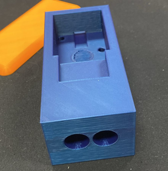
In order to see if the electronic components fit perfectly in the box we designed, we printed a first prototype without the fillets, as this geometric adjustment can cause some problems when printing and for a first prototype we decided to opt for the simplest version. As for printing the lid, we decided to print it using the final model, and we noticed that the print wasn’t as perfect.
The first print piece had a number of errors that we had to correct. In particular, the thickness was exaggerated, the internal space wasn’t large enough, among other details that had to be changed.
Here you can see how the first attempt at printing turned out:
Second attempt#
Modelling changes#
Compared to the previous model, in this next model we’ve reduced the thickness of the case, changed the area where the earplugs will be stored and the holes for connecting the electronic components.
With regard to the changes made to the box, in order to change the button hole so that an on and off switch could be inserted, we transformed the circle made earlier into a rectangle and extruded cut again.
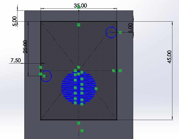
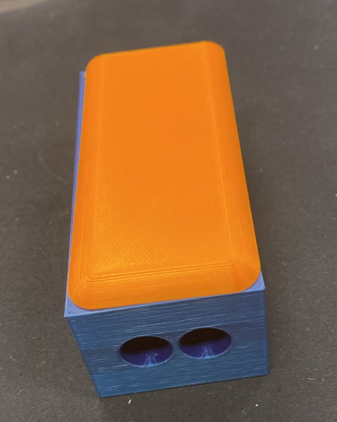
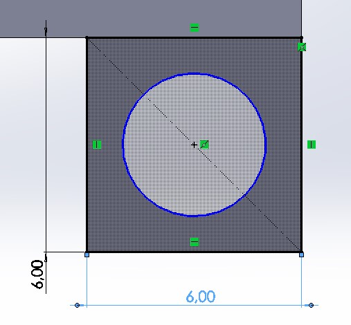
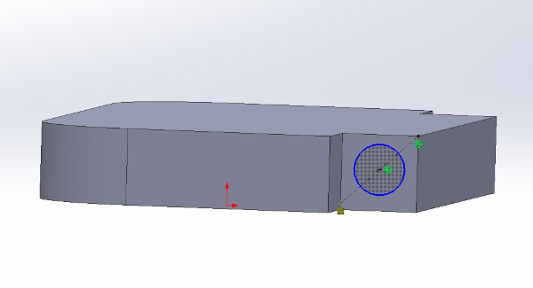
In addition, we created two holes in the top of the box, in the part where the earplugs will be inserted. To do that we have created two parallel planes and consequently perpendicular to the plane of the top of the box. On these planes we made two circles inside two squares and extruded boss/base from the space between the circles and the squares. As you can see in the image.
Finally, we build a hole into which the piece that will close the box will fit
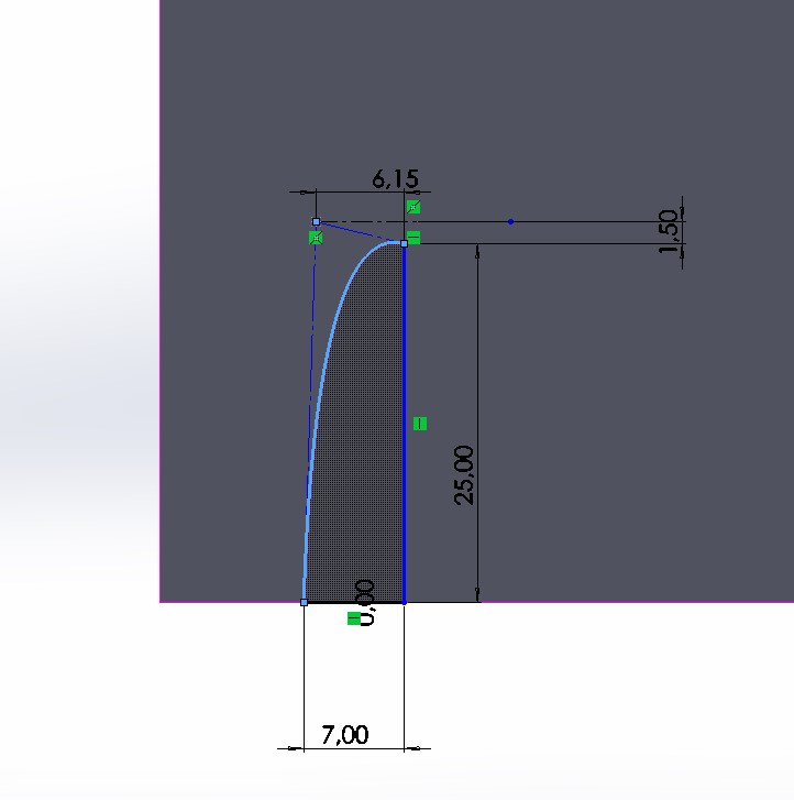
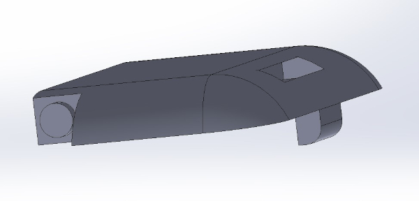
To build the cap that will cover the earplug area, we start by constructing a piece with this shape.

Then we applied some fillets to acchive a better shape. In the part where no fillet was applied, we drew circles the same size as the holes that were made in the box.
Then we extrude the boss/base of these circles, forming small cylinders measuring 1.50 mm.
Finally, we built a salience to be able to close the box, and we a small indentation to make it easier to open.
We’ve added a locking mechanism for the part where the earplugs will be stored, which you can see in the following image.
You can also watch this video to get a better idea of how it all works.
Printing Process#
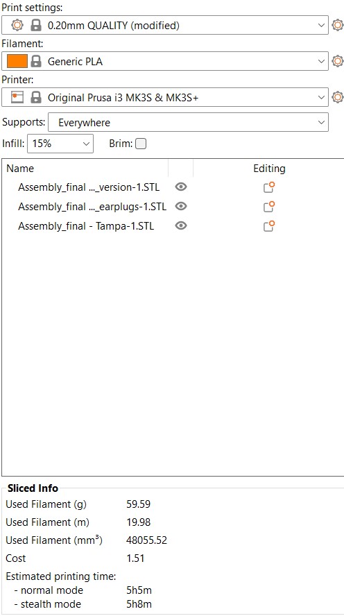
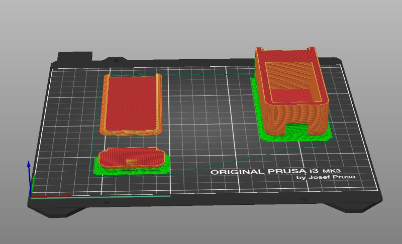
We printed our second piece attempt on the day of the pre-jury hakaton. To do this, we transferred the 3 pieces to Prusa Slicer, using the following settings. This time we added supports to the box and the earplug cover, because these had more complex parts that might need more support.
And we print them separately, the following image is just to illustrate the process.
However, we had some problems with the printing process, specially with the cover parte, the 3D printer starts to colapse and we had to stop the printing two times.

Fortunately, at the end we managed to get the result we expected.